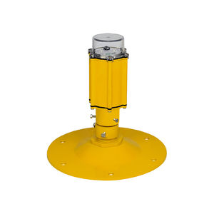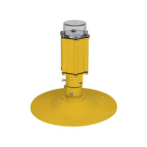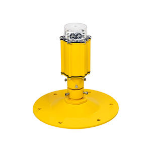
Approach light AL-056-08-WHfor heli-platformsLEDflashing
Add to favorites
Compare this product
Characteristics
- Type
- approach
- Domain
- for heli-platforms
- Technology
- LED
- Other characteristics
- white, flashing, steady
- Power
15 W
Description
The Heliport APPROACH lights are steady and flashing omnidirectional white lights.
According to ICAO ANNEX 14, volume II, an approach lighting system should be provided at a heliport where it is desirable and practicable to indicate a preferred approach direction.
These lights should form a cross to create the Approach lighting system.
The approach lighting system is a row of three lights at 30 m intervals and a crossbar of five lights on 18 m at a distance of 90 m from the perimeter of the FATO.
Where there is the need to make the final approach course more conspicuous, additional lights spaced uniformly at 30 m intervals should be added beyond the
crossbar. The lights beyond the crossbar may be steady or sequenced flashing, depending upon the environment.
The mounting system is elevated, fixed on a base plate with a frangible coupling
The casing is made of powder-coated aluminum
The diffuser is made of clear polycarbonate UV protected
Electrical characteristics
The power supply can be a heliport controller. In this case, the control is also made in three steps from the heliport controller. Power input can be low voltage, 48 V DC or it can work in constant current when the distance from the heliport controller to the lights is long and this will generate a big drop of voltage on cables.
Optionally it can be powered at 90-230V, 50/60Hz but the light fixtures will no longer have the dimming function
If the sequenced flashing is needed then a flashing controller must be added to the control system
Environment
APPROACH elevated lights were tested for working environments from -50 to + 50 °C
The degree of protection is IP 67
Catalogs
No catalogs are available for this product.
See all of Signalight‘s catalogsRelated Searches
- Color light
- Airport beacon
- Airport runway light
- Obstacle light
- Configuration light
- Aircraft beacon
- Approach lighting system
- Helideck beacon
- Mounting lighting
- Landing lighting system
- Position light
- IR light
- Wind cone
- Taxiway light
- Airport floodlight
- Wind cone with mast
- Runway edge light
- Heli-platform light
- PAPI light
- Helicopter lighting system
*Prices are pre-tax. They exclude delivery charges and customs duties and do not include additional charges for installation or activation options. Prices are indicative only and may vary by country, with changes to the cost of raw materials and exchange rates.


